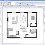
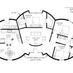
Essential Guide to Electrical Floor Plan Symbols
Electrical floor plans are crucial documents that provide a visual representation of the electrical system in a building. They help understand the layout of electrical components, circuits, and connections, ensuring safe and efficient operation.
Using standardized electrical floor plan symbols is essential for proper interpretation and communication between engineers, architects, and electricians. These symbols represent various electrical components, devices, and pathways, providing a comprehensive understanding of the electrical system.
Types of Electrical Floor Plan Symbols
Electrical floor plan symbols can be categorized into different types based on their function:
- Light fixtures: Symbols for different types of lighting fixtures, such as ceiling lights, wall sconces, and recessed lights.
- Switches: Symbols indicating the location and type of switches, such as single-pole, double-pole, and three-way switches.
- Receptacles: Symbols representing electrical outlets for plugging in appliances and devices.
- Circuits: Lines and arrows depicting the paths of electrical circuits, including branch circuits, lighting circuits, and power circuits.
- Panels: Symbols for electrical panels, including circuit breakers, fuses, and switches.
- Grounding: Symbols indicating grounding points and connections for safety protection.
Understanding Electrical Floor Plan Symbols
To comprehend electrical floor plans, it is essential to familiarize oneself with the standardized symbols. Each symbol represents a specific component or function in the electrical system. By using a symbol legend or a code book, individuals can identify and interpret the symbols accurately.
Understanding the location and type of electrical components from a floor plan is crucial for electrical professionals. It enables them to troubleshoot issues, plan renovations, and ensure compliance with electrical codes and standards.
Importance of Electrical Floor Plan Symbols
Electrical floor plan symbols play a vital role in various aspects of building design and maintenance:
- Electrical system planning: Floor plans assist in designing and installing new electrical systems, ensuring proper component placement and circuit layout.
- Building renovations: During renovations, floor plans provide a reference for updating or modifying electrical systems, ensuring safety and functionality.
- Troubleshooting and maintenance: Floor plans help locate electrical components, such as switches, panels, and outlets, for troubleshooting and maintenance purposes.
- Code compliance: Floor plans with accurate symbols demonstrate compliance with electrical codes and standards for building inspections and permitting.
- Communication: Clear and standardized symbols facilitate seamless communication between different parties involved in electrical projects.
Conclusion
Electrical floor plan symbols are an essential part of any electrical system. By understanding and using these symbols correctly, engineers, architects, and electricians can create, install, maintain, and renovate electrical systems effectively. Standardized symbols ensure accurate communication, promote safety, and facilitate efficient building operations.

It S Electrical

House Electrical Plan Diagram Symbols Blueprint

Create An Electrical Plan Roomsketcher Help Center

Electrical Symbol Floor Plan Symbols How To

Floor Plan Symbols And Abbreviations To Read Plans Foyr

Electrical Symbols S Browse 1 329 553 Stock Photos Vectors And Adobe

Cad Vector Electrical Plan Symbols Library Post Digital Architecture

Electrical Blueprint Symbols

It S Electrical

Understanding Floor Plan Symbols Maximize Your Design Precision