Plan Section And Elevation Of Houses: Essential Aspects
Understanding the plan section and elevation of houses is crucial for architects, engineers, and homeowners alike. These drawings provide a comprehensive representation of a building's design, allowing for accurate construction and visualization. Here are some essential aspects to consider when working with plan section and elevation drawings:
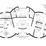
Plan View
The plan view, also known as the floor plan, is a horizontal cross-section of a building at a specific level. It typically includes the following elements:
- Walls and Partitions
- Doors and Windows
- Rooms and Spaces
- Furniture and Fixtures
- Dimensions and Annotations
Section View
The section view is a vertical cross-section of a building, revealing the internal structure and relationships between spaces. It shows the following details:
- Wall Heights
- Floor and Ceiling Levels
- Structural Elements (e.g., beams, columns)
- Mechanical and Electrical Systems
- Roof Construction
Elevation View
The elevation view is a drawing that shows the external appearance of a building from a specific direction. It typically includes the following:
- Exterior Walls
- Roof Shapes and Pitches
- Windows and Doors
- Exterior Finishes and Materials
- Landscaping and Site Context
Importance of Accuracy
Accuracy is paramount when creating plan section and elevation drawings. Incorrect measurements or errors can lead to construction delays, cost overruns, and safety hazards. Therefore, architects and engineers must meticulously review and verify all drawings before construction begins.
Coordination and Collaboration
Creating plan section and elevation drawings often involves collaboration between architects, engineers, and contractors. Effective communication and coordination ensure that all parties are on the same page and that the final structure meets design intentions and building regulations.
Conclusion
Plan section and elevation drawings are essential tools for understanding, designing, and constructing buildings. By considering the aspects discussed above, architects, engineers, and homeowners can create accurate and effective representations of their projects. These drawings not only facilitate successful construction but also enhance visualization and communication throughout the building process.

Scheme Of The Tested Single Family House A Front Elevation B Scientific Diagram

Two Level House Elevation Section Ground And First Floor Plan Details Dwg File One Plans Small Design

Residential Building With Detailed Plan Section Elevation Specifications Plinth Design

Simple House Elevation Section And Floor Plan Cad Drawing Details Dwg File Cadbull

Pin On Quick Saves

House Plan With Section And Elevation In Dwg File Cadbull

House Plan Section And Elevation View Dwg File Cadbull

Construction Plan Drawings Elevation Cross Section And Ground Scientific Diagram

Solved Need A Simple House Plan Site Sectional Chegg Com

Floor Plans House Layout